*FIC Injectors all come factory with a EV6 plug. A EV6 to Nippon/Denso adaptor is included with out kits.
Fuel Injector Clinic can adapt a fuel injector to match any top feed application. The 8x1000cc high performance injectors will be data mated, E85 compatible, with a Lifetime warranty
This injector set is precisely matched using Fuel Injector Clinic's proprietary Data Match Technology. Each injector is individually serial numbered and the results are provided on the Data Match Sheet providing the most complete flow matching and latency value information available in the industry today.
Fuel Injector Clinic injectors are flow tested and rated at 43.5psi (3Bar) at 90deg F fuel temperature using CF-16B calibration fluid.
Superior short pulse width control and state of the art matching make these injectors easy to tune and provide great drivability.
Fuel Injector Clinic injectors are set up to and include all o-rings needed to fit the factory application for the listed vehicle. If you are using aftermarket or other unusual setups please contact us prior to placing your order to make sure you receive injectors that fit properly.
Every injector is covered against failure caused by defects in original manufacture by our lifetime warranty.
What is Fuel Injector Clinic’s Data Match Technology?
Fuel Injector Clinic’s Data Match Technology is used to create a very comprehensive information sheet, which customers receive with each injector set*. It provides the most complete flow matching and latency value information available in the industry, featuring dynamic slope flow rates and individual latency deviation values.
When Fuel Injector Clinic’s Data Match Technology information is correctly input into your Electronic Control Unit (ECU), the data will allow the ECU to dictate PRECISELY the right amount of fuel to combine with the air in your intake port to consistently achieve the correct Air/Fuel Ratio (AFR), which means you’ll get more complete combustion in your combustion chambers.
Fuel Injector Clinic has developed a specialized flow bench in collaboration with ECMTuning, Inc., which accurately measures the microscopic volume of fluid dispensed while it is being operated by a car’s ECU. This method provides tuners with the best possible injector data to successfully tune their cars.
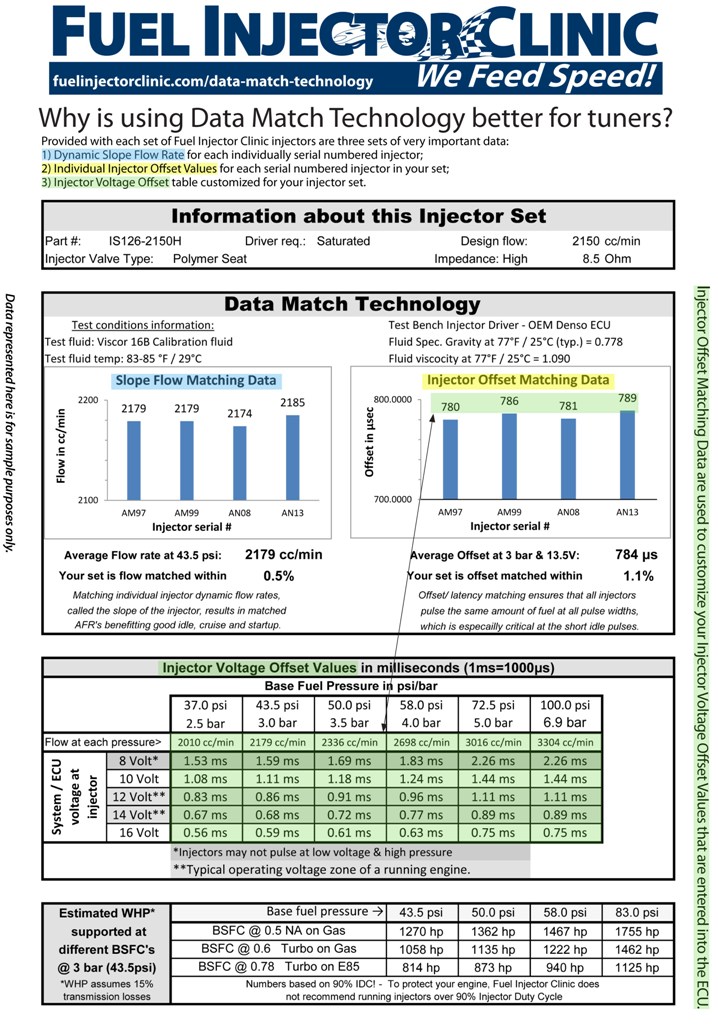
The Data Match Technology information sheet provided with each set of Fuel Injector Clinic injectors matched using this method gives you three sets of very important data:
- Dynamic Slope Flow Rate for each individually serial numbered injector,
- Individual Injector Offset Values for each serial numbered injector in your set,
- Injector Voltage Offset table.
1. Dynamic Slope Flow Rate for each individually serial numbered injector.
This slope flow rate, expressed in cc/min at the pressure and temperature listed on the sheet, represents the linear flow rate that the ECU can use when calculating the pulse width (length of time to open) it needs to send to the injector. Since the ECU typically only accepts one value for all injectors, it is clear how important it is that this flow rate is as consistent as possible from one injector to another. The “Dynamic Slope Flow” box of the flow sheet shows how well matched your injectors are. To get the most accurate results, you will typically use the “Average Slope flow value” below the individual data to input into your ECU.
The individual slope flow data represented in this table is calculated from at least 1,000 pulses per injector, making Data Match Technology the most detailed information provided by any performance injector company at this time.
NOTE: Testing for these values is done at 3 Bar (43.5psi) using 16B calibration fluid at 90°F (a fluid with similar specific gravity to gasoline, which is widely used in the automotive industry as a “safe” testing fluid closely resembling gasoline.) If you run a different base pressure or a different fuel, you would need to adjust the flow rate in your tuning software accordingly. (More on flow rate can be found in our tech information.)
2. Individual Injector Offset Values for each serial numbered injector in your set.
The offset value (often referred to as the dead time, lag time, or latency value) is used by the ECU to compensate for the loss of flow during the opening and closing period of each pulse, where full (aka constant or linear) flow has not been achieved. While the numerical values needed for data entry in the ECU are listed in the “Injector Voltage Offset” table at the bottom of the Data Match Technology information sheet, the accurate matching of this characteristic for each injector ensures that the ECU, which uses only one correction value for all injectors, is able to instruct the injectors to dispense exactly the right amount of fuel.
WHY? While offset matching will improve the result with all injectors, it is especially critical for injectors with a large flow rate (for example1000cc and larger) at idle or light throttle. This is because the offset correction length applied by the ECU represents a much higher percentage of total pulse width, so any error is greatly amplified.
For example, a 2150cc injector may need a 1.1msec total pulse width to dispense the right amount of fuel at idle, of which 0.7msec is the offset correction at 13 volt, resulting in an effective pulse width of 0.4msec. If there is a 0.2msec difference in offset value from one injector in that set to another, the effective pulse width could vary by 0.2msec/0.4msec=0.5 or 50% within the same set, which would easily cause enough variation in AFR to result in a misfire. Using the same variance in a smaller injector, like a 650cc, which requires a 2.3msec pulse width and has a 1.0msec offset value, results in an effective pulse width of 1.3msec. If the 650cc injector set has the same 0.2msec variance from one injector to another as the 2150cc injector in the example above, it is only a 15% fueling error, which is much easier for the motor to forgive.
Also at play is the fact that in large performance injectors the effective pulse width range you are operating in (0.3 to 0.8msec) is SO short that the injector is only performing an incomplete valve opening, which is an action that is much more challenging to repeat consistently than the fully settled opening at 6 or 7msec. Therefore a well-matched injector set is easy to tune and performs well in idle, cranking and other light throttle conditions.
3. Injector Voltage Offset table.
The bottom of the Data Match Technology information sheet lists average offset values for the type of injector you purchased. This data is very time consuming to collect because it requires our injector technicians to perform detailed offset testing at all the voltages and pressures listed (typically five voltages and five pressures.) A test at one voltage and one pressure is derived from test data accumulated from pulsing the injector hundreds of times at 0.5msec intervals from 2msec to 18msec (10% to 90% duty cycle at 6000rpm), representing almost 10,000 data points. (See the four graphs below of this level of testing with even more detail in low pulse width area). You can’t just do this for one injector, it must be representative of the whole spectrum of injectors. So Fuel Injector Clinic tests a minimum of 16 injectors in order to collect a good average. Multiply the 16 injectors by the 25 voltage and pressure combinations in your offset table and you can see why this 4,000,000 point process is not for the faint of heart.
Bottom line: Fuel Injector Clinic provides more in depth data with each injector set than any other company in the aftermarket performance industry. The method by which we gather and present data as well as characterize injectors is at the forefront of the industry.
So when you’re studying your Data Match Technology information sheet, keep in mind that what may appear to be a simple excel spreadsheet of injector data, or a simple drop-down selection of base map inputs from an ECU manufacturer (that we may well have supplied), is actually the result of a highly technical and time-consuming process where enormous amounts of data are amassed. And, Fuel Injector Clinic’s investment in our proprietary Data Match Technology works for you every time you run your car.
Information for ALL graphs shown.
X-axis:
- Effective pulse width in milliseconds. Most ECU’s are programmed in either milliseconds (msec = 1/1,000th of a second) or microseconds (µsec = 1/1,000,000th of a second)
- The four lines (red, black, green and yellow) on the graphs have been corrected for the offset measured on each injector, therefore showing the linear approximations going through the origin (zero). This is done to bring the injector graphs closer together for visual benefit.
Y-axis:
- Injector flow in cc/min. This is a calculated value based on flow per injector stroke converted back to cc/min flow assuming a 6000rpm pulse rate. This is done to represent flow values in units most familiar to tuners. We can easily provide the flow per stroke values for interested tuners, since you do not idle your car at 6000rpm.
The four different Fuel Injector Clinic (FIC) injectors shown are all latest-technology Bosch high impedance injectors driven by a saturated injector driver from a recent model Mitsubishi ECU.
Information Specific to individual graphs
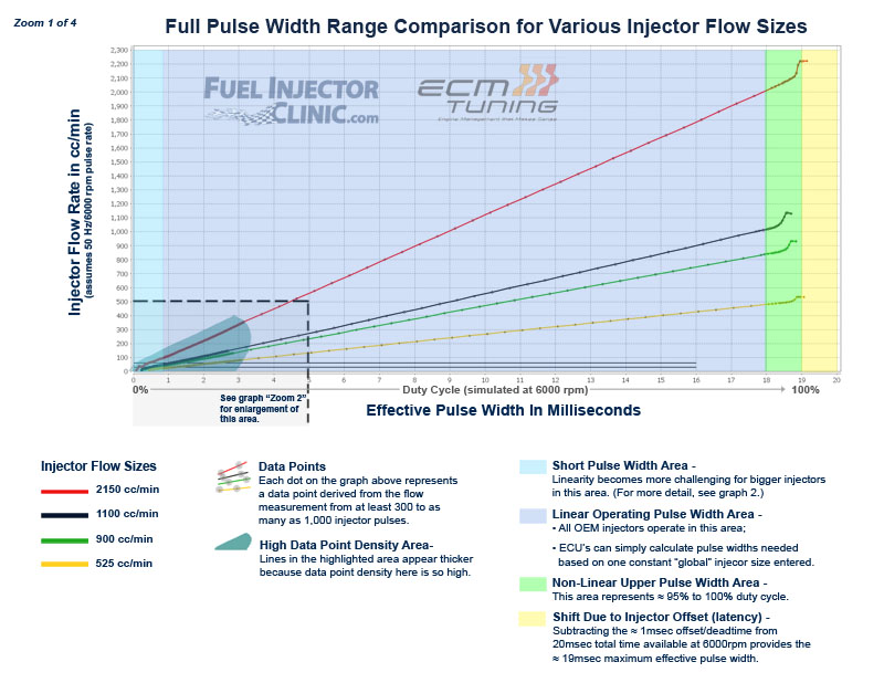
Zoom 1 of 4
This graph shows the full range of the injector being pulsed in a motor at 6000rpm or 50Hz, where a 20ms second pulse would represent 100% duty cycle, taking up all the time available for two revolutions of the motor (assumes a 4-stroke motor application for the injector).
The other graphs below zoom in on the low pulse width area to show why this is the most challenging condition for an injector.
Injector flow from pulse widths between 0.8msec and 18msec (shaded in gray) is the linear portion of injector operation (Note how the lines - red, black, green and yellow - in this section are basically straight slopes.)

Zoom 2 of 4
This graph shows effective pulse widths from 0 to 5 milliseconds.
The opening “bumps” in the initial operating range of the injector (far left) are clearly identifiable.
The two black horizontal lines (30 and 60 on the y axis) are approximate fuel consumption at idle and light cruise throttle for a 4 cyclinder engine on gasoline. Note how the two smaller injectors operate in their linear operating range between the idle and cruise lines, whereas the 1100cc/min (black) is a little “bumpy” in that area and the 2150cc/min (red) is clearly in the non-linear area
Also note how the data points progressively become closer together from right to left as the non-linear operating range is approached. On the right data points are every 0.5 msec, in the center section data points are every 0.1msec and on the left the data points are still too close to define at this zoom level.

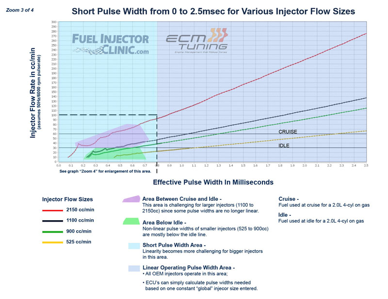
Zoom 3 of 4
This graph shows effective pulse widths from 0 to 2.5 milliseconds.
Here there is more detail between the idle and cruise lines . It becomes increasingly obvious why the smaller injectors are much easier to tune based on their very linear operation in this area.
The 1100cc/min injector still has a reasonably linear operating range in the idle and just above idle pulse width range. While there are some non-linear “bumps,” the variations are likely small enough not to be detectable by the tuner.
The 2150cc/min injector graph clearly shows how non-linear the operation of an injector of this size is in the area between idle and cruise. While this is obviously not beneficial to tuning a motor, it should be noted that ALL types and brands of large (approximately 1200cc/min and larger) injectors face this issue, since it is related primarily to the flow size of the injector, and the extremely short pulse width required for the minute amounts of fuel required at idle.

Zoom 4 of 4
This graph shows effective pulse widths from 0 to 0.8 milliseconds.
This is an extreme level of detail shown, since we are now able to discern individual data points at close as 0.004msec (or 4 msec = 4/1,000,000th of a second).
Clearly visible are the “bumps” for all injectors. The “bumps” are made by the valve reaching its maximum opening limit (where the line peaks on the graph) and then bouncing back from hitting the limit (where the line makes a downward slope, creating the valley).
While these non-linear flow areas of the injector are not very conducive to the matching process, Fuel Injector Clinic includes some of this data to help make the injectors work better for the tuner in this area. Looking at the 1100cc/min injector graph (black) note how the valve bounces a few times until the flow settles into its linear range as the pulse width length is extended. Note that this graph is zoomed to the 0.25 to 0.8millisecond range, or around 4% (very small part) of the 19ms total operating range.


